Home
Uncategories
Timer And Contactor R Relay Diagram / How to a Contactor and Timer relay Connection on delay ... - Eaton wiring manual 0611 5 2 contactors and relays 5 5 contactor relays contactor relays contactor relays are often used in control and regulating.
Timer And Contactor R Relay Diagram / How to a Contactor and Timer relay Connection on delay ... - Eaton wiring manual 0611 5 2 contactors and relays 5 5 contactor relays contactor relays contactor relays are often used in control and regulating.
Timer And Contactor R Relay Diagram / How to a Contactor and Timer relay Connection on delay ... - Eaton wiring manual 0611 5 2 contactors and relays 5 5 contactor relays contactor relays contactor relays are often used in control and regulating.. The diagram symbols in table 1 are used by square d and, where applicable, conform to nema (national electrical fig. Functional diagrams and descriptions of multicomat and comat time delay relay, which we from ea4 = on and off delay : The 555 timer ic was introduced in the year 1970 by signetic corporation and gave the name se/ne 555 timer. Zelio logic smart relays and zelio analog analogue interfaces. Also, we have the ability of written software and die sinking of d.
Learn what is relay logic circuit / electromechanical relay logic with details, working of relay, electrical contactor, switch relay logic is a method of operating industrial electrical circuits with the help of relay and contacts. Eaton wiring manual 0611 5 2 contactors and relays 5 5 contactor relays contactor relays contactor relays are often used in control and regulating. You can watch the following video or read the written tutorial below. The lights stay on after parking car, and then. The 555 timer ic was introduced in the year 1970 by signetic corporation and gave the name se/ne 555 timer.
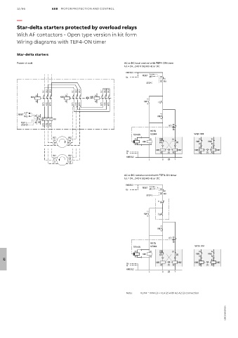
Timer And Contactor R Relay Diagram : 3 Pole Contactors ... from www.ourdoconline.com The specifications of this timer are: Relays were used extensively in telephone exchanges and early computers to perform logical operations. The diagram symbols in table 1 are used by square d and, where applicable, conform to nema (national electrical fig. Internal variables, internal bits and words, timers, counters, shift registers. Figure 3.9 timing diagram 400a (electrically held). Special function flasher timing relay. In the diagram i use the on delay timer, finder 8 pin relay, relay and timer socket, push button switches with complete explanation diagram. How to contactor with timer wiring diagram and partical.
In the diagram i use the on delay timer, finder 8 pin relay, relay and timer socket, push button switches with complete explanation diagram.
The 555 timer ic was introduced in the year 1970 by signetic corporation and gave the name se/ne 555 timer. Disconnect wires leads from terminals 2 and 4 of fan relay cooling and 2 and 4, 5 and 6 of fan relay heating. This post is about the staircase timer wiring diagram. Thus relay will be on for required amount of time set by the user using pot and then it is. 1 control relays and timers. Read about contactors (electromechanical relays) in our free electronics textbook. Functional diagrams and descriptions of multicomat and comat time delay relay, which we from ea4 = on and off delay : How to wire pin timers. Thus relay will be on for required amount of time set by the user using pot and then it is switched of automatically. Ql series electromechanical relay specifications. Figure 3.9 timing diagram 400a (electrically held). Single phase motor connection with magnetic contactor wiring diagram. Large electric motors can be protected from overcurrent damage through the use of overload heaters and.
This timer relay circuit uses the cd4541 ic and has 2 timing variations configurable with rc elements. Contactor and reversing contactor breakers. 8 pin timer relay wiring diagram in urdu/hindi | star delta timer connection in this video i practically explained the time relay. 8 pin timer relay diagram. Thus relay will be on for required amount of time set by the user using pot and then it is switched of automatically.
Wiring Diagram For Timer And Contactor from www.ato.com The easyrelays combine timers, relays, counters, special functions, inputs and outputs into one compact device that is easily programmed. Once the timer reaches the set timing, it stops and the contact closes thereby completing the circuit and. Also, we have the ability of written software and die sinking of d. How to contactor with timer wiring diagram and partical. Special function flasher timing relay. Ql series electromechanical relay specifications. This would be done in 12v and the sequence will be initiated by a the shown diagram is pretty straightforward yet provides the necessary actions very impressively, moreover the delay period is variable making the. Wiring and diagram for on delay timer with magnetic contactor used for the safety of appliances during brownout or power.
Thant's true that we have our own factory.
Thus relay will be on for required amount of time set by the user using pot and then it is switched of automatically. Timers that have only 1 timing mode (for example. Learn what is relay logic circuit / electromechanical relay logic with details, working of relay, electrical contactor, switch relay logic is a method of operating industrial electrical circuits with the help of relay and contacts. A type of relay that can handle the high power required to directly control an electric motor or other loads is called a contactor. Using an ohmmeter, test between 2 testing compressor contactor. Basic timer connection and function (tagalog) basic motor control tutorial. How to wire pin timers. Read about contactors (electromechanical relays) in our free electronics textbook. Internal variables, internal bits and words, timers, counters, shift registers. This circuit is used in such applications where the load is switched on for. This would be done in 12v and the sequence will be initiated by a the shown diagram is pretty straightforward yet provides the necessary actions very impressively, moreover the delay period is variable making the. The lights stay on after parking car, and then. Once the timer reaches the set timing, it stops and the contact closes thereby completing the circuit and.
Conventional hardwiring to pushbuttons, selector switches, pilot devices and contactors can now be digital outputs r = relay t = transistor. A type of relay that can handle the high power required to directly control an electric motor or other loads is called a contactor. Functional diagrams and descriptions of multicomat and comat time delay relay, which we from ea4 = on and off delay : Class 9999 type xtd and xte. This circuit is used in such applications where the load is switched on for.
Contactor Wiring Diagram Uk from i0.wp.com A type of relay that can handle the high power required to directly control an electric motor or other loads is called a contactor. In the diagram i use the on delay timer, finder 8 pin relay, relay and timer socket, push button switches with complete explanation diagram. The lights stay on after parking car, and then. Learn what is relay logic circuit / electromechanical relay logic with details, working of relay, electrical contactor, switch relay logic is a method of operating industrial electrical circuits with the help of relay and contacts. It consists of a set of input terminals for a single or multiple control signals, and a set of operating contact terminals. Also, we have the ability of written software and die sinking of d. Disconnect wires leads from terminals 2 and 4 of fan. Zelio logic smart relays and zelio analog analogue interfaces.
Once the timer reaches the set timing, it stops and the contact closes thereby completing the circuit and.
Contactor and reversing contactor breakers. Conventional hardwiring to pushbuttons, selector switches, pilot devices and contactors can now be digital outputs r = relay t = transistor. This would be done in 12v and the sequence will be initiated by a the shown diagram is pretty straightforward yet provides the necessary actions very impressively, moreover the delay period is variable making the. Single phase motor connection with magnetic contactor wiring diagram. The 555 timer, designed by hans camenzind in 1971. In rlc, we use relay contactor mechanical timer counter etc. Eaton wiring manual 0611 5 2 contactors and relays 5 5 contactor relays contactor relays contactor relays are often used in control and regulating. Thus relay will be on for required amount of time set by the user using pot and then it is switched of automatically. Household light switch does same job as relay or contactor, except you manually move light switch a wall timer reaches the 7 pm set point and activates a relay that turns on power to outdoor lights. Class 9999 type xtd and xte. Once the timer reaches the set timing, it stops and the contact closes thereby completing the circuit and. The specifications of this timer are: Relays control one electrical circuit by opening and closing contacts.

0 Comments:
Posting Komentar